- Item type
- Object
- Provenance
- Presented by the Marconi Corporation.
- Primary inscriptions
- "MARCONI / AUTO ALARM EQUIPMENT / TYPE M" printed on celluloid plaque upon lower section of front surface.
- Object type
- Radio communication
- Dimensions
- Height: 960mm Width: 350mm Depth: 310mm
- Inventory No
- 24207
- Accession Number
- 2004-9/536
Description
Marconi Type M Vigilant Auto-Alarm, in grey-painted cabinet with three units mounted in drawers. This model was introduced prior to World War Two and was used until it was superseded by a similar type in the mid 1950s.
Auto Alarms were first introduced around 1919 when the first of the thermionic Triode valves became available in what was the era of Spark transmitters and Magnetic detector receivers utilising Morse code on the Calling and Distress frequency (500kHz - 600M). The development was likely prompted by the loss of the Titanic as few other than large passenger liners kept a continuous 24Hrs Radio watch. Other single operator vessels kept 12 hour watches based on ship's time - not GMT. Hence the Titanic's collision being outside of normal watch keeping was missed by all but one ship, the 'Carpathia some distance away from the scene of the disaster.
To differentiate the auto alarm signal from Morse it was agreed that it would take the form of four second dashes separated by one second spaces. The receiving apparatus specification allowed tolerance for the timing of the signal.
Marconi devised a electro-mechanical Selector to measure the timing sounding alarms after three consecutive correctly Spaced Dashes. The design preceded the introduction of the Vigilant and in a slightly modified version continued to be used until the late 1950s.
This instrument is made up of three units: a Receiver, the Selector and an Interrupter (test oscillator).
The Selector essentially consists of a Vibrating Reed feeding a hand started Phonic motor running at 600 R.P.M. Electro-magnetic clutches engage various cams, pawls and hotches rotating on a shaft. The contraption rattled merrily away year in year out in response to Morse signals until an Alarm signal arrived. The various mechanical parts clocked the timing and incremented the total until the requisite number was registered at which point the alarm was raised.
The SOS signal and Distress message would follow after a short delay.
The Morse era ended with the introduction of GMDSS for shipping in 1999/2000.
The receiver was fixed tuned to 500 kHz with only minor adjustment at installation through tiny access holes either side of the centrally located meter. On the left hand side adjustment could be made via a screwdriver to a vane type Condenser (Capacitor) to optimise the setting with the ship's main aerial slung between the two masts. The setting was recorded by inspecting tiny numerals just visible through the adjustment hole.
The left hand hole adjusted the automatic gain control (AGC) such that the receiver would respond to the test oscillator (ICW Interruptor) mounted in the bottom section of the cabinet. Prior to going off-watch, the Radio Officer would check that the Receiver operated correctly by using the Interruptor. Once again the setting was recorded by viewing numerals through the hole.
The central dial (marked "OFF", "HTV", "4", "3", "2", "1") reads the Anode currents of the four valves making up the Receiver. That allows checks to quickly decide whether any of the four valves were faulty needing replacement.
Two coloured bulbs, one green, the other red identifies any failure in the Low Tension (L.T.) valve heater chain, and also the High Tension (H.T.) 120V Anode supply.
Related Items
More related items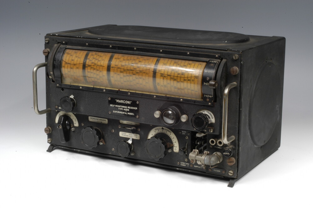 'Marconi' Self-Monitoring Receiver Type AD98, by Marconi Company, English, Mid 20th CenturyInventory Number 22068
 Carton For Marconi Valve Type GTIC, by Marconi Company, English, Mid 20th Century`Inventory Number 96026
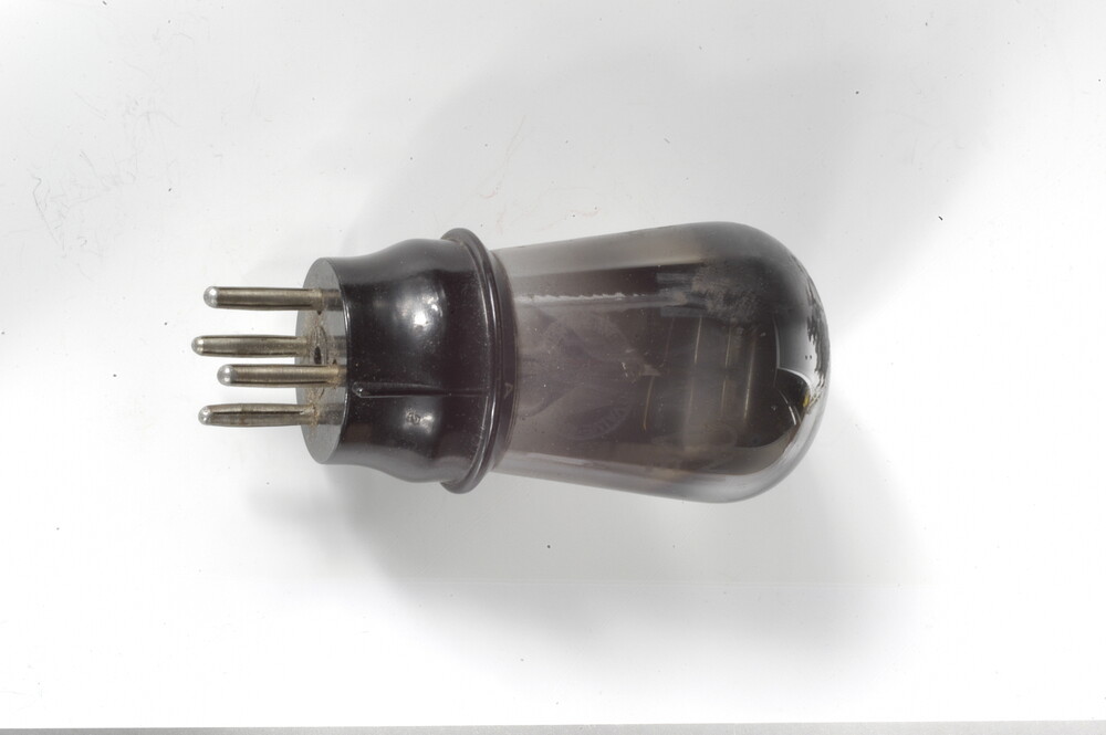 Marconi Radio Valve Type DEHL210, by Marconi Company, English, 20th CenturyInventory Number 46377
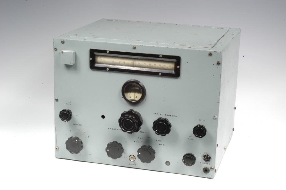 Marconi Receiver CR100, by Marconi Company, English, Mid 20th CenturyInventory Number 81277